Current Status: Phase 1 - Design and Development – Testing in Progress
The first prototype has been built and is currently undergoing testing to gather data for future improvements and potential upgrades to the next version.
Project Overview
To develop an actively controlled UAV to explore flight dynamics, gain deeper insights into control algorithms, and further enhance my skills in embedded systems.
Key Components:
- Frame: 3D-printed structure reinforced with carbon fiber legs for durability and lightweight strength.
- Thrust System: EDF (Electric Ducted Fan)
- Active Control System: Four custom-designed vanes for precise thrust vectoring to control Yaw, Pitch, and Roll.
- Flight Computer: Powered by The Capable Flight Computer, emphasizing sensor fusion, communication, telemetry, and advanced control algorithms.
Design and Architecture
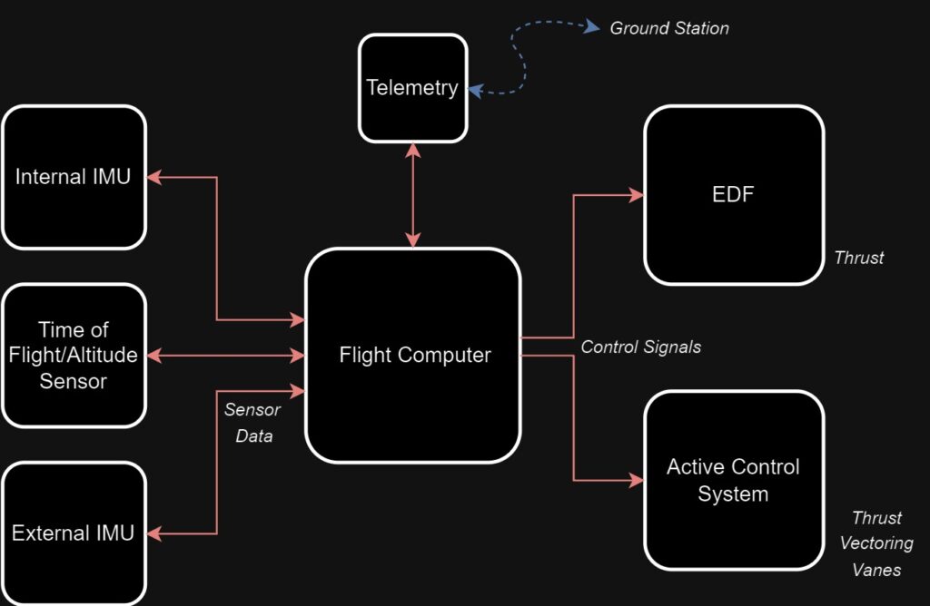
High-Level System Architecture:

Sensor Subsystems
Integrated Sensors (Flight Computer):
| Sensor/Module | Name | Purpose |
|---|---|---|
| Magnetometer | LIS3MDL | Sensor Fusion: Orientation / Altitude Estimation |
| IMU (Accelerometer, Gyroscope) | BMI088 | |
| Pressure Sensor | BMP388 | Pressure, Temperature, and Altitude Measurement |
| Power Monitor | INA219 | Current and Voltage Measurement |
| PWM Driver | PCA9685 | Active Control System Actuation |
External Sensor:
| Sensor/Module | Name | Purpose |
|---|---|---|
| IMU (Magnetometer, Accelerometer, Gyroscope) |
BNO08x | Sensor Fusion: Orientation / Altitude Estimation |
| Time of Flight | VL53L1X | Near-Ground Altitude Measurement |
| Telemetry Radio | LR24F 2.4G | 2-way Communication Between Ground Station and Hopper |
| GPS | – | Currently Not Mounted |
Mechanical Subsystems
Structure and Design:
- 3D-Printed Body: Made using PLA+, ensuring a lightweight structure with adequate strength.
- Carbon Fiber Legs: Solid carbon fiber rods absorb impact and distribute landing forces effectively.
- Modular Design: Allows easy addition or removal of compartments and support elements for flexible configurations.
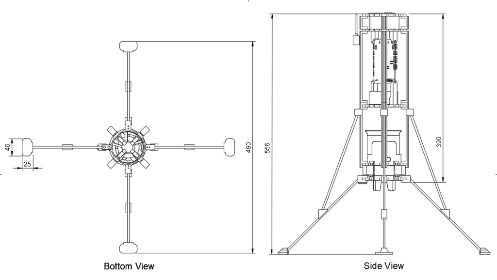
Dimensions (mm):
- Landing Leg Span: The legs are spaced 490mm apart, forming a stable circular footprint to prevent toppling.
- Landing Leg Base: Each leg’s base measures 40mm x 25mm for solid ground contact.
- Total Height: The current version of Hopper stands 556mm tall from the ground to the top.

Communication and Telemetry Subsystem
Telemetry Radio (LR24-F 2.4G): 2.4GHz LoRa-based long-range telemetry radio.
- Range: ~10 Kilometers with proper antenna and surrounding conditions.
- Function: Bidirectional communication between Hopper and the ground station.
- Communication Protocol: Connected to Flight Computer through UART protocol with configurable Baud rate.
- Antenna: Currently using 2.4G 3dBi 11cm antenna.
Flight Computer Communication
Internal Sensor & Module Communication:
| Sensor/Module | Protocol | Internally Connected to |
|---|---|---|
| Magnetometer | I2C | Navigation Computer |
| IMU (Accelerometer, Gyroscope) | I2C | Navigation Computer |
| Pressure Sensor | I2C | Navigation Computer |
| Power Monitor | I2C | Main Flight Computer |
| PWM Driver | I2C | Main Flight Computer |
External Sensor & Module Communication:
| External Sensor/Module | Protocol | Connected to (via exposed peripheral) |
|---|---|---|
| IMU (Magnetometer, Accelerometer, Gyroscope) | I2C | Navigation Computer |
| ESC (for EDF) | I2C and PWM | Main Flight Computer through PWM Driver |
| Servos (Active Control System) | I2C and PWM | Main Flight Computer through PWM Driver |
| Telemetry Radio | UART | Main Flight Computer |
| GPS | UART | Navigation Computer (Currently not mounted) |
Power Subsystem
- Power Source: Both the EDF and Flight Computer are powered by a single high-discharge lithium polymer (LiPo) battery to provide the necessary power for efficient operations.
- Active Control System: Integrated within the Flight Computer, it is powered by dedicated regulators to ensure stable voltage levels.
- Battery Monitoring: The Flight Computer continuously monitors battery health and makes decisions based on remaining capacity. It also logs power data and transmits it via the telemetry radio for ground monitoring.
Ascent and Descent Control System
- Thrust-to-Weight Ratio (TWR): The current EDF generates up to 1.250kg of thrust, giving the vehicle a TWR between 1.5 and 2.0. This ensures smooth liftoff, controlled flight, and enough margin for maneuvering and acceleration.
- Sustained Flight Capability: Maintaining a TWR above 1.0 guarantees sustained vertical flight. As the project evolves, upgraded EDFs or vehicle weight adjustments will ensure this ratio is maintained.
- EDF Thrust Control: The flight computer regulates ascent and descent by precisely throttling the EDF to maintain stable flight.
Active Control System
- Thrust Vectoring Vanes: The Hopper uses four independently actuated vanes to control altitude and orientation (roll, pitch, and yaw).
- Servo Control: Each vane is controlled by a dedicated servo motor, allowing independent actuation for precise maneuverability.
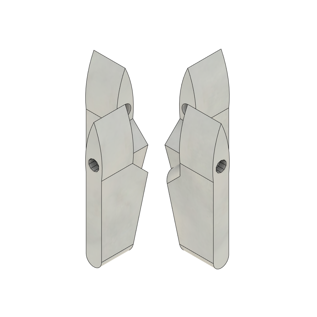
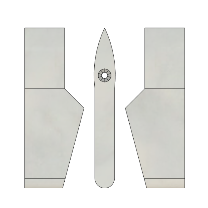
- Design Iteration: The vane design is currently in development, and the primary focus is testing to optimize performance and control.
Current Vanes Design:


Ground Control System
- Current Development: The Ground Station is under development. Telemetry data and commands are exchanged via a serial console/terminal at this stage.
- Future Capabilities: The final Ground Station will feature real-time telemetry plots and data visualization from the Hopper.
- Command Capability: It will also enable direct commands transmission to the Hopper, supporting two-way communication.
- Previous Experience: I have designed Ground Systems using MATLAB App Designer and Python scripts and am currently exploring other approaches.
Safety and Failsafe System
- Power Distribution Logic: Power from the main battery is split between the EDF (via ESC) and the flight computer. The FC continuously monitors power levels and will only initiate operations if the voltage exceeds a preset threshold. In flight, it can execute a controlled landing if power drops unexpectedly.
- Near-Ground Altitude Sensing: Currently mounted ToF Laser Ranging Sensor measures altitude up to 4 meters, ensuring precise landings. When within this range, the laser sensor becomes the primary altitude sensor, replacing the barometer and GPS for better accuracy.
Challenges and Solutions
- Thrust Vectoring: Optimizing vane design for responsive control.
- Communication: Inter-MCU synchronization to ensure real-time data processing.
- Active Control: Optimizing control systems gains and precise altitude adjustments.
Phase 2 (Future Plans)
- Component Testing: Bench tests for EDF and vane movement.
- Tethered Flight Testing: Evaluate control system stability and responsiveness by conducting tests with the Hopper securely tethered. This approach ensures safety while gathering performance data for further improvements.
